- 要导出带纹理文件的obj,并且把纹理文件拷贝到obj所在目录,需要在导出的path mode选项处,选择“copy”
- 被导出的对象的材质可以是Pricipled BSDF, 不能是Pricipled Diffuse。至于其他的材质类型是否可以,我们还不确定。而且材质不能使用node,纹理处不能是multiple等用了其他结点的纹理。只能是直接的纹理。
- 被导出对象的材质的纹理图片不能是内部未提取的图片。如果是blend中未提取的图片,则需要通过如下方式把图片文件提取出来:


draw工具就像普通的画笔工具,能在mesh表面刻画“凸”或者“凹”的图案。需要注意的是,这里刻画出的轨迹会相对的光滑。因为它的刻画过程会把周围一定范围内的点都按照距离刻画轨迹的距离做相对运动。 例如下图所示:

球面上凸出的部分,除了轨迹的最中央发生了移动外,其周围的点也发生了移动。
Draw Sharp工具相对Draw而言,刻画的轨迹会更锐利。其刻画轨迹周围的点只会进行很小的移动,或者,就不会移动。如下图所示:

Clay工具对mesh的操作逻辑和前两者是一样的。不同的是,刻画轨迹对周围点的影响方式。Clay对刻画轨迹距离近的点影响会更大,而其对远处的点影响会成一个急剧下降的趋势。参考下图所示:

上面是Clay工具,下面是Draw工具分别对同一个点在同样参数下(包括操作半径,强度等)应用10次操作后的结果。上图明显更加顿,下图明显更加尖。可以设想如果是Draw Sharp工具,那应该会更加尖。
Clay Strips工具其操作的逻辑与前面不一样了。但时其刻画轨迹对周围点影响的方式却与Clay工具一致。不一样的是,Clay Strips要求操作时必须是一条刻画的线条轨迹,不能是单点操作。单点操作时,此工具是无效的。如果来回在一条线上重复应用此工具则会得到如下效果:

此工具相对Clay能刻画出更好的线条。
Layer工具有点像Draw,其操作逻辑和Draw也是一样的。但其刻画轨迹对周围点影响的方式不太一样。Layer工具会多0.5倍操作半径以内的点影响很大,但时操作0.5倍半径后会急剧减少。这种影响能够给mesh刻画出一个立体层的感觉。

Layer最终形成的效果和Clay Stripes的效果有点像,但不同的是,Clay Stripes是对刻画轨迹的旁边起作用。
Inflate操作工具与前面的类似,不过其对刻画轨迹周围点的影响行为又不一样,Inflate能对周围给出更光滑的影响能力。如下图所示:

Blob的操作方式与Inflate类似,但Blob对周围点的影响能力成球面变化。如下图所示:

图中左侧是Blob, 右侧是Inflate。可见Inflate提供的影响更加光滑,Blob对周围的影响以0.5倍操作半径的球面影响力。
Crease工具的操作方法也与前面类似,不同的仍然是对周围顶点的影响能力。Crease能对周围点形成比较强的圆周方向的吸引能力。将周围顶点拉得离自己更近,以此来形成“皱痕”。如下图所示:

图中右侧是Blob,左侧是Crease。可见Blob明显的把周围的点往四周推开形成球面,而Crease把周围的点进一步聚拢而形成褶皱。
此操作如其名字一样,能使操作半径内的顶点更加光滑。
此操作能让半径内的顶点更加平坦
Fill操作与Flatten操作类似,不同的是Fill是以操作半径和方向上最高的点为目标来变平坦,而Flattern是以中间点。如下图所示:

图中左侧是Flatten,右侧是Fill。可见Fill操作的平坦位置更高一些。
Scrape与Fill类似,不过会把平面'刮'得更平整
这个工具与Crease类似,不过它能在褶皱边的时候尽量避免对旁边顶点的“捏起”。下图是Multiplane Scrape与Crease操作的对比:

图中左侧是Crease操作,右侧是Multiplane Scrape操作。可见Crease操作对边界的“捏起”现象很严重,而Multiplane Scrape操作让局部范围内(操作半径范围内)的几何形体维持不变。
Pinch操作与Crease操作类似,不同的是,Crease在把周围顶点聚拢的同时在凸起或者凹下,而Pinch操作只做单纯的聚拢操作。下图是Pinch与Crease操作的效果对比:

图中,左侧是Crease操作,右侧是Pinch操作。从效果对比看,Crease和Pinch都有把四周的点像内聚拢的操作,但Pinch聚拢更加明显,尤其是对近距离的点。而Crease有凸起的效果,Pinch却没有。
直接对顶点做拉申移动操作。拉伸操作会对操作半径以内的顶点起到连带作用。
这个操作很类似与Grab,不同的是这个操作对顶点的拖拽对周围的点的影响更加光滑。下图是Elastic Deform 与Grab操作的效果差别:

图中,左边是Grab操作效果,右边是Elastic Deform操作效果。
Snake Hook操作也是拖拽操作,但与前面Grab和Elastice Deform都不同的点在于,Grab和Elastice Deform都是先指定对一个点操作,然后再由这个点来影响一定范围内的其他点。而Snake Hook操作是对指定范围内所有的点进行拖拽操作。
Thumb也是拖拽操作,不过它的拖拽仅限制于对顶点做垂直于法线方向的平面内进行拖拽操作。也就是说,这个拖拽会抑制顶点沿法线方向拖拽。
这个操作模拟了弹性表面的“揉捏”操作
这个Nudge类似Pose操作,不过Nudge的操作是更加轻的"揉捏"
这个操作能让mesh表面指定区域内的顶点群做绕点击中心的旋转运动,示例如下图所示:

slide relax也是模拟“揉捏“操作,但不同的时,它的操作不是按照固定点做“揉捏”。而是按照操作的位置来“滑动”。它与Nudge的区别就像Snake Hook与Grab的区别。其操作效果如下图所示:

这个操作会简化mesh表面的三角形分布,移除短三角形的边,构建大的三角形。操作效果如下图所示

需要注意的是,此操作只在Dynamic Topo模式下有效
blender sculpting操作中的mask能够给mesh中的一些顶点加上标识,让前面的操作多这些点的影响减少或者无效。

上图中,黑色的部分是mask标识的顶点部分。此时对该区域的刻画操作已经无效或者影响减低。
hide操作类似于Mask,只不过它更加彻底,能够让那些不想操作的点直接无视新的刻画操作,并且在操作的时候直接不可见。

图中在一个球进行Deform操作后,左右本应该对称,但因为左侧部分点被Box Hide掉,所有那些点无视了Deform操作的影响。
能够对整个mesh应用多种过滤器,包括随机过滤,光滑过滤,膨胀过滤等。下图是对整个mesh应用random过滤的效果:

此处整理一些从使用角度来整理和分类的一些blender操作
操作步骤如下:
操作步骤如下:
操作步骤如下:
不同于实体建模的表面网格(mesh)建模被广泛应用在艺术品,游戏角色等3D模型的构建之中。而在mesh建模发展的历史过程中,最惹人瞩目的技术恐怕非“曲面细分”(subdivision)算法莫属。而曲面细分算法的各种方案中又以Catmull-Clark方案最为应用广泛。致力于研究曲面细分算法的研发和优化的工程师们在业界满载着荣誉。例如在曲面细分算法上做出突出贡献的Jos Stam就曾经获得过SGI公司颁发的"计算机图形奖",并两次获得“奥斯卡科技成果奖”(这也侧面说明曲面细分算法对电影事业的重大影响)。
下面将简要的解析Catmull-Clark算法。
后文来自http://www.rorydriscoll.com/2008/08/01/catmull-clark-subdivision-the-basics/
How exactly does a 3D application decide how to subdivide a control mesh? Well, there are a few different subdivision schemes out there, but the most widely used is Catmull-Clark subdivision. Since the original paper by Ed Catmull and Jim Clark, there have been a number of improvements to the original scheme, in particular dealing with crease and boundary edges. This means that although an application might say that it uses Catmull-Clark subdivision, you’ll probably see slightly different results, particularly in regard to edge weights and boundaries.
The original rules for how to subdivide a control mesh are actually fairly simple. The paper describes the mathematics behind the rules for meshes with quads only, and then goes on to generalize this without proof for meshes with arbitrary polygons. I’m going to go through a very simple example here to show what happens when a mesh gets subdivided. I’m going to be concentrating solely on non-boundary sections of the mesh for simplicity. Also, the example uses a 2D mesh, but again this is only for simplicity, and the principles expand to 3D without change.
There are four basic steps to subdividing a mesh of control-points:
1. Add a new point to each face, called the face-point.
2. Add a new point to each edge, called the edge-point.
3. Move the control-point to another position, called the vertex-point.
4. Connect the new points.
Easy, right? The only question left to answer is, what are the rules for adding and moving these points? Well, like I wrote earlier, this really depends on who implemented it, but I’m going to show the original Catmull-Clark rules using screenshots from Modo. This doesn’t mean that these are the rules that Modo applies, but it should be fairly close.
Here’s the example mesh I’m going to be using:
No prizes for guessing which face we’re going to be looking at. I’ve made it a little bit skewed because that makes things more interesting. If you’re wondering about the double edges around the boundary, I’m going to be writing about those at a later date, so be patient! For now I need them to make the boundary hold shape, but they can be safely ignored for the purposes of this article.
Firstly, we need to insert a face point, but where? Well this is easy, it just needs to go at the average position of all the control points for the face:
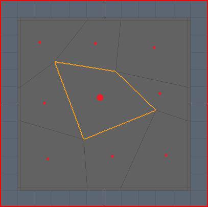
I’ve drawn red dots approximately where each new face-point will go. The big dot is obviously the face-point for the highlighted face. The location for each dot is simply the sum of all the positions of the control-points in that face, divided by the number of control-points.
Now we need to add edge-points. Because we’re not dealing with weighted, crease or boundary edges, this is also fairly simple. For each edge, we take the average of the two control points on either side of the edge, and the face-points of the touching faces.
Here’s an example for one edge-point, in blue, where the control points affecting its position are pink, and face-points are red. Note that the edge points don’t necessarily lie on the original edge!
For the highlighted face only, I’ve drawn all the roughly where each new edge-point will go in blue:
This step is a little bit more complicated, but very interesting. We’re going to see how we place the vertex-points from the original control points, and why they get placed there. This time, we use a weighted average to determine where the vertex-point will be placed. A weighted average is just a normal average, except you allow some values to have greater influence on the final result than others.
Before I begin with the details of this step, I need to define a term that you may have heard used in regards to subdivision surfaces – valence. The valence of a point is simply the number of edges that connect to that point. In the example mesh, you can see that all of the control points have a valence of 4.
Alright, I’m going to dive into some math here, but I’m also going to explain what the math actually means in real terms, so don’t be put off!
The new vertex-point is placed at:
(Q/n) + (2R/n) + (S(n-3)/n)
where n is the valence, Q is the average of the surrounding face points, R is the average of all surround edge midpoints, and S is the control point.
When you break this down, it’s actually fairly simple. Looking at our example, our control-points have a valence of 4, which means n = 4. Applying this to the formula, we now get:
(Q/4) + (R/2) + (S/4)
Much simpler! What does this mean though? Well, it says that a quarter of the weighting for the vertex-point comes from the average of surrounding face-points, half of it comes from the surrounding edge midpoints, and the last quarter comes from the original control-point.
If we look at the top left control point in the highlighted face, Q is the average of the surrounding face-points, the red dots:
R is the average of the surrounding edge midpoints, the yellow dots. Note that the yellow dots represent the middle of the edge (just the average of the two end points) which is a little bit different from the edge-points we inserted above because they don’t factor in the nearby face-points.
S is just the original control-point, the pink dot:
Below is my rough approximation of where all these averages come out, using the same color scheme as before. So the yellow dot is the average of all the yellow dots above, and the red dot is the average of all the red dots above.
Now all we do is take the weighted average of these points. So remember that the red dot accounts for a quarter, the yellow dot accounts for half, and the pink dot accounts for the final quarter. So the final resting place for the vertex-point should be somewhere near the yellow dot, slightly toward the pink dot, roughly where the pink dot is below:
So now I hope you can see why the control point is going to get pulled down and to the right. All the surrounding points just get averaged together and weighted to pull the vertex around. This means that if a control-point is next to a huge face, and three small faces, the huge face is going to pull that vertex towards it much more that the small faces do.
One other thing you can see from this is that if the mesh is split into regular faces, then the control point won’t move at all because the average of all the points will be the same as the original control point. The pull from each face-point and edge midpoint gets canceled out by a matching point on the other side:
The final step is just to connect all the points. Confusingly, Modo has two ways to subdivide a mesh which actually return slightly different results. I don’t know why this is, or how the subdivision schemes differ, but they are close enough for all intents and purposes to call the same. For clarity, I’m using a screenshot from Modo where I have subdivided using the SDS subdivide command. For the highlighted face only, I’ve drawn the new face-point in red, the new edge-points in blue, and the moved vertex-points in pink:
Below is an overlay of the original control mesh for reference. As expected, you can see that the top left control-point gets pulled to the right. The same process is applied to all faces, resulting in four times as many quads as we had previously.
If you look at the formula for moving the control-point to its new location, you can see that not only are the immediate neighbor points used, so are the all the rest of the points in the adjoining faces. How much any single one of these surrounding points affects the control-point isn’t very clear from the original formula. This information is actually really easy to find out just by substituting in the surrounding points into the original formula.
I’m making the assumption from hereon out that all of the surrounding faces are quads to make things easier on myself. Also, I’m not going to write down each step of the expansion here since it got pretty big, but at the end, I got the following weights:
Control-point weight = (4n-7) / 4n
Edge-neighbor weight = 3 / 2n^2
Face-neighbor weight = 1 / 4n^2
I’m using the term edge-neighbor to denote a neighboring point sharing the same edge as the control point, and face-neighbor as a neighbor that only shares the same face as the control-point. In the picture below, the edge-neighbors are cyan, and the face neighbors are yellow. Note that for quads, you have exactly n edge-neighbors, and n face-neighbors.
Applying this formula to various different valences, you get the following weights for a single point of the given type:
| Valence | Control | Edge Neighbor | Face Neighbor |
| 3 | 5/12 | 3/18 | 1/36 |
| 4 | 9/16 | 3/32 | 1/64 |
| 5 | 13/20 | 3/50 | 1/100 |
| Infinity | 1 | 0 | 0 |
What does this mean? If we look at a the valence-4 row, you can see that if you move a face-neighbor, that’s going to affect the position of the vertex-point by 1/64th of however much you move it. So if you move it 64 cm on the x-axis, then the resulting vertex-point will move 1 cm in the same direction. I tested this scenario out in Modo, and it seems to match up very closely.
Clearly, the edge-neighbors are weighted more heavily than the face-neighbors, and the control-point itself always the most influence on the final vertex-point location. Remember though, each point represents a different thing (control-point, edge-neighbor, face-neighbor, nothing) depending on which particular face is getting subdivided!
It is interesting to note what happens as the valence gets larger and larger. The control-point influence tends towards 1, while all the neighboring points tend to zero. The reverse is also true, where at valence-4, the control-point weight is about 0.56, at valence-3 it is only 0.41 which means it is getting pulled around by its neighbors a lot more.
一、获取天空盒子的六张图片
1、将建好的模型打开,在模型里面添加一个正方体(将正方体的大小调整合适),将其移动到模型的正中间


2、在编辑模式下全选中正方体,将其标记缝合边。然后再UV展开。

3、打开uv编辑器,新建一个图像。 生成类型选择“UV栅格图”。

4、打开"UV Editing"界面, 视图着色方式选择“实体-纹理”,在“UV编辑器”界面点击图片选择刚刚新建好的图像,然后再将正方体UV展开。 之后再回到之前界面。

5、将视图着色方式选择“实体-纹理”, 打开着色节点编辑器,选中正方体然后新建一个材质,然后添加节点:Texture-Image Texture、Shader-Glossy BSDF。将Shader-Glossy BSDF里的Roughness值调成0.


选中正方体,将其平滑一次。再将正方体表面细分细分次数为5~6次。

6、接着是烘焙, 先选中里面的小球体,然后选择渲染模块里的烘焙,烘焙类型选择“合并结果”, 渲染器选择"Cycles"渲染器,然后点击烘焙。

7、 最后一步,把界面切换至“UV Editing”界面,然后将烘焙后的图片导出保存。

二、图片的处理
1、先把图片按分界线切割出来,然后将每一张图片的像素放大到1024*1024(这里要保证图片的清晰程度)
2、将六张图片在ps上通过旋转、翻转等方法拼接在一起,然后导出,将每一张图片对应的坐标关系一重命名的方法标注好
制作思路:先建立两个同心球体,一大一小,大的在外面小的在里面,然后通过让给外面的大球体添加一种发光的材质以及
一、天空盒子六张图片制作方法
1、打开blender后在原有的正方体上直接添加一个经纬球。然后将经纬球整体放大4倍(这里的倍数对结果不造成影响,为了方便操作即可)。

2、在编辑模式下以X轴为分割线将球的上半部分选中,接着在“网格”中找到“分离”将其按“选中项”分离开。

3、然后分别将球体的上半部分和下半部分UV展开。
4、接着全选中球体里面的正方体,在编辑模式下找到“边”中的“标记缝合边”,最后在将正方体UV展开。( 这里的标记的边缘是告诉Blender,当我们使用UV菜单中的“unwrap”选项时,这条边缘两侧的面在UV贴图中不应该粘在一起。相反,他们将分开,因为Blender的UV贴图的目标是最小化拉伸。 )

5、打开UV编辑器,点击“图像”导入准备好的两张图片,然后再新建一个图像(宽度和高度可调可不调)、生成类型选择“UV栅格图”。


6、打开“UV Editing”

7、然后再编辑模式下全选中正方体,视图着色方式选择“实体-纹理”,在“UV编辑器”界面点击图片选择刚刚新建好的图像,然后再将正方体UV展开。接着分别选中球体的上半部分和下半部分,然后点击图片分别选择刚刚导入的那两张图片(这个过程不需要再UV展开)。


8、然后再切换至Layout界面或者Default界面(初始3D界面),视图着色方式选择“实体-纹理”,接着在侧边属性栏里将渲染模块里的渲染器调成Cycles渲染器,然后打开着色节点编辑器。选中球体的上半部分,接着点开侧边栏里属性材料模块里新建一个材料属性(为了方便最好给这个属性取一个名称),然后添加节点,球体的上半部分要添加的节点有:Texture-Image Texture、Shader-Esmission、Input-Texture Coordinate。(着色编辑器下各种节点的含义)节点连线和属性值如图。


然后选中球体的下半部分,以同样的方式添加节点:Texture-Image Texture、Shader-Esmission、Input-Texture Coordinate、Shader-Mix Shader、Shader-Transparent BSDF。

接着再选中里面的正方体,添加节点:Texture-Image Texture、Shader-Glossy BSDF。将Shader-Glossy BSDF里的Roughness值调成0.


9、分别依次选中球体的上下部分和正方体,将其都平滑一次。(平滑操作是怎么定义的?平滑操作能使物体达到什么样的效果?)

10、再分别将球体的上下部分以及正方体表面细分(球体的上下部分的细分次数为4次、正方体的细分次数为5~6次)(曲面细分的原理是什么?能达到什么效果?用在什么地方?这里的曲面细分只是为了减小球体表面的图像的方块大小,以及让球体更加的圆滑。)。


11、先选中里面的小球体,然后选择渲染模块里的烘焙,烘焙类型选择“光泽”,影响里只勾选“直接光”,然后点击烘焙。

12、最后一步,把界面切换至“UV Editing”界面,然后将烘焙后的图片导出保存。

二、图片的处理
1、先把图片按分界线切割出来,然后将每一张图片的像素放大到1024*1024(这里要保证图片的清晰程度)

2、 2、将六张图片在ps上通过旋转、翻转等方法拼接在一起,然后导出,将每一张图片对应的坐标关系一重命名的方法标注好 。
3、每一张图片的对应坐标如图

4、旋转关系:
ny----水平翻转一次
py----先顺时针旋转90°,然后水平翻转一次
pz----垂直翻转一次
nx-----逆时针旋转90°
nz-----先顺时针旋转90°,然后水平翻转一次
px-----垂直翻转一次,然后再水平翻转一次

obj格式是WaveFront公司推出的一种3d模型格式,该文件通过点,线,自由参数曲面等信息来描述mesh模型。也算是比较通用的3d交互格式。但是在通过blender, threejs等系统导入此格式时却需要特别注意一个点。那就是对参数曲面的支持问题。
大部分的开源系统是不支持参数曲面的。尤其要注意以下几点:
因此,在通过软件导出便于第三方系统解析的obj时,需要对导出的几何类型做一些限制。例如在配置导出曲线选择nurbs还是polyline时,都需要选择polyline。

bpy.data - all data in your blend file.bpy.context - data in the current active view.bpy.ops - tools which typically operate on bpy.contextbpy.datagives you access to all data in the blend file, every object, material, compositing node etc. in every scene (also the scenes themselves) can be accessed through bpy.data.
Generally, you would either loop over all datablocks, or get a specific item by name.
bpy.contextis context sensitive, it depends on the area your mouse is over, the selections you make and so on. It lists only a subset of data such as the current scene, the active object etc. This is an easy way to have a script work on whatever object is selected rather than having to know it's name beforehand (bpy.context.object refers to the active object, or is None if there is no active object, bpy.context.selected_objects is a list of the selected objects).
bpy.opsis where you can access tools (operators) organized in categories, e.g. bpy.ops.object.select_all() (object is the category for object-related operations, together with select_all it is the operator name and () calls it). These perform the actions typically accessed in the user interface, referenced by menu items and key shortcuts. When you search through the spacebar menu, you are seeing a list of all operators, which are available in the current context.
These three prefixes are the most common but there are others. bpy.types contains all the types or "classes" used within Blender. You will also use bpy.utils if you write an addon (mainly to register and unregister classes derived from bpy.types, e.g. to create own operators, menus, panels...). There are also some other modules available that aren't prefixed with bpy such as mathutils and bmesh.